Privacy statement: Your privacy is very important to Us. Our company promises not to disclose your personal information to any external company with out your explicit permission.
No need for PLC or microcontroller to provide proportional solenoid valve control
Abstract: The linear change acts as a variable resistance voltage divider connected to the DIM input of the LED driver (operating as an electromagnetic PWM driver) and the digital potentiometer. This circuit drives DC electromagnets ranging from 6V to 40V DC registration, using only the 6V to 40V DC power supply of the electromagnet.
Some industrial electromagnets found in proportionally controlled hydraulic systems usually drive microcontrollers or programmable logic controllers (PLCs). This complex driver usually requires several different logic and control supply voltages. (The purpose of this proportional control is to plunge the solenoid valve to any position and leave there.) One set and pull down the solenoid drive, however, should not require the processing power of an expensive PLC or a microcontroller. Ideally, it should work on its own power supply voltage.
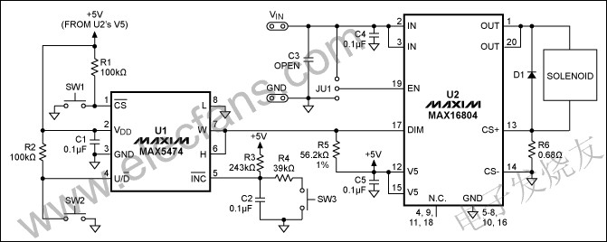
Whether the circuit in Figure 1 meets these requirements while occupying only a small surface mount footprint. U2 is a 350mA driver with built-in analog and PWM dimming control (MAX16804 available), usually used to drive high-brightness light-emitting diodes. In this application, its open-drain output (OUT) and current detection terminal (CS) are directly connected to the electromagnet terminal. The maximum current of the solenoid valve is set by R6. This circuit drives DC electromagnets ranging from 6V to 40V DC registration, using only the 6V to 40V DC power supply of the electromagnet. This test uses a LEDex 24V pull coil with a rated current of up to 290 mA.
Control Valve, Flow Control Valve, Hydraulic Control Valve, Proportional Directional Control Valve

figure 1. This small, surface mount, digital drive circuit provides a proportional electromagnet driver.
U1 (MAX5474) is a 32-tap, non-volatile, linearly changing digital potentiometer. As a variable resistor connection, a 100kΩ variable resistor is formed inside and the R5 voltage divider generates an analog voltage of 0V to 3.17V at the DIM input of U2. After activation, by suppressing the potentiometer of SW1 and setting the direction of change using SW2 (open, closed for the next), you can increase the voltage of this switch with each SW3 (SW1 off). The third step is available, so the loop traversal of the 32-press and released SW3 ranges from 0V to 3.17V. Equation 1 gives the approximate voltage at the dim sum (VDIM) at the position of the sliding end:
VDIM ≈ 5V ((N-1) 3225.8Ω) / ((N-1) 3225.8Ω + R5) (Eq. 1)
Where R5 = 56.2kΩ, N is N tap steps (≤32 when 0≤n). In R3, the pulses of SW3 deflected by R4 and C2 increase / decrease.
U2 is powered by the solenoid valve power supply (24V in this case). U1 is powered by U2's V5 pin, a 5V power supply, and a current source of up to 2mA. The capacitors C1, C4 and C5 bypass the supply voltage at their respective IC pins.
In order to adapt to the PWM application of action U2, the freewheeling diode D1 allows current to flow through the electromagnetic coil every time the power switch is turned off (200 times per second). U2 provides indirect short-circuit and thermal protection to prevent it from over-current and short-circuit damage to the coil or additional conditions cause short-circuit output. Connect VIN (enable) or GND (disable) U2 of the EN input (pin 19) controlled by jumper JU1. Table 1 summarizes the electromagnetic circuit conditions for different positions in Figure 1.
Table 1. Solenoid valve drive circuit data

Figure 2 shows the operation of the electromagnetic drive voltage and current pulse generating circuit at 26% duty cycle. This represents the electromagnetic duty cycle voltage and current requirements of 32.4mARMS solenoid coil energized to pull the electromagnetic plunger at a distance of 0.0312in.

figure 2. From these electromagnetic voltage and current waveforms in Figure 1, a distance of 0.0312in plunger with a duty cycle of 26% and a duty cycle of 76% of 0.3312in is generated.
Figure 3 shows the operation of the electromagnetic drive voltage and current pulse generating circuit at 76% duty cycle. This represents the electromagnetic duty cycle voltage and current requirements of 211mARMS solenoid coil energized to pull the electromagnetic plunger 0.312in distance.

image 3. The voltage and current waveforms of these coils Figure 1 The circuit produces a plunger distance of 0.31 in.
October 09, 2024
September 24, 2024
Письмо этому поставщику
October 09, 2024
September 24, 2024

Privacy statement: Your privacy is very important to Us. Our company promises not to disclose your personal information to any external company with out your explicit permission.

Fill in more information so that we can get in touch with you faster
Privacy statement: Your privacy is very important to Us. Our company promises not to disclose your personal information to any external company with out your explicit permission.